

Views: 0 Author: Site Editor Publish Time: 2026-07-22 Origin: Site


Catastrophic hose failure often traces back to a single engineering oversight: miscalculating pressure and temperature parameters. When a high-pressure line ruptures or a thermal leak occurs, the operational consequences are severe. Unplanned downtime halts production lines, while hazardous spills introduce serious safety and environmental liabilities. Many operators fall into the trap of relying solely on baseline nominal ratings. They look at a catalog number and assume it covers their needs, failing to account for dynamic, real-world operating conditions. Pressure spikes, rapid valve closures, and ambient thermal extremes push materials far beyond their static limits. Precise data collection across specific pressure and temperature metrics is non-negotiable. You need accurate, documented parameters to ensure safe, compliant, and reliable industrial hose selection. Understanding exactly what data to gather will protect your infrastructure and personnel from preventable failures.
Dynamic Over Static: Operating pressure data must account for system surges, spikes, and pulsations, not just steady-state maximums.
Dual Temperature Tracking: Accurate specification requires data on both the internal media temperature and the external ambient temperature, as both degrade hose materials differently.
The Derating Reality: As operating temperatures rise, the maximum allowable working pressure of a hose decreases; calculating this inverse relationship is critical for safety.
Application-Specific Nuance: Fluid types dictate the necessary safety margins, with compressible gases (air) and hazardous liquids (fuel) requiring distinct pressure-temperature evaluations.
Expectation vs. Service Life: High-quality construction and formal documentation of both upper and lower operational limits prevent premature material fatigue and yield predictable service lifespans.
A successful specification process hinges on clear criteria. You aim for zero safety incidents, maximum service life, and strict regulatory compliance. Achieving this requires moving beyond guesswork. Every component in a fluid transfer system must handle the exact physical forces applied to it. If the pressure exceeds the structural integrity of the reinforcement layer, the hose bursts. If the temperature exceeds the elastomer's threshold, the material degrades, hardens, or melts.
Industry professionals rely on the STAMPED framework to evaluate requirements. Within this established standard, Temperature and Pressure act as the primary structural constraints. They dictate what materials you can use and how thick the reinforcement must be. You cannot finalize size or ends without first locking down the thermal and pressure boundaries.
Size: Inside diameter, outside diameter, and overall length requirements.
Temperature: Internal fluid temperature and external environmental temperature.
Application: How and where the assembly will be used, including flexing and routing.
Material: The specific fluid or gas being conveyed.
Pressure: Maximum working pressure, including spikes and vacuum ratings.
Ends: The specific fittings and coupling methods required.
Delivery: Testing, packaging, and certification requirements.
There is a direct relationship between high-quality material selection, environmental conditions, and long-term operational stability. Cutting corners on initial procurement often leads to frequent replacements. A hose rated exactly for your baseline pressure might survive for a few months. However, a properly specified assembly that accounts for environmental heat and pressure surges will deliver a predictable, extended service life. This reduces maintenance labor and replacement frequency.
Matching a system's baseline output directly to a maximum rating is dangerous. Nominal ratings assume steady, ideal conditions. Real industrial environments are rarely ideal. Pumps cycle on and off. Valves slam shut. Sun exposure bakes the exterior. If you only use the nominal operating pressure without documenting safety margins and operational variables, you risk catastrophic failure during routine system fluctuations.
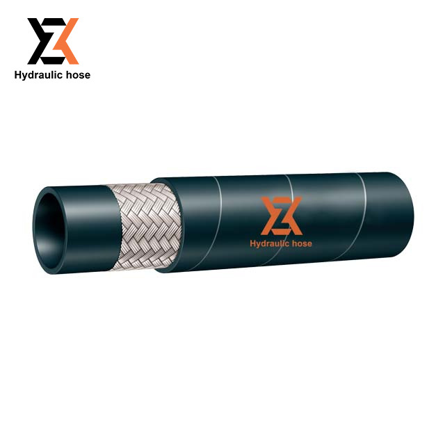
You must map your system's continuous operating pressure against the manufacturer's Maximum Allowable Working Pressure (MAWP). The MAWP represents the absolute highest pressure the hose can safely handle under continuous operation. You need to gather data using standard measurement metrics like PSI, Bar, or MPa. Ensure your system's normal operating pressure stays comfortably below the MAWP to provide a buffer for unexpected variations.
Defining the total pressure envelope requires knowing both the upper and lower internal pressure limits. Modest low-pressure systems might operate at just 1 Bar, focusing more on flow rate than containment strength. In contrast, extreme multi-bar hydraulic or heavy industrial applications demand heavy wire reinforcement. Documenting the absolute minimum and maximum normal operating pressures establishes your baseline requirement.
| Pressure Metric | Definition | Application Relevance |
|---|---|---|
| Operating Pressure | The normal, continuous pressure of the system during standard operation. | Must always remain below the MAWP. |
| Surge/Spike Pressure | Transient, rapid increases in pressure caused by valve closures or pump cycles. | Dictates the true maximum pressure the hose must withstand. |
| Test Pressure | Non-destructive pressure applied during manufacturing to verify assembly integrity. | Typically 1.5x to 2x the MAWP. |
| Burst Pressure | The destructive limit where the hose physically ruptures. | Used to establish safety factors (e.g., 4:1 ratio). Never for operation. |
Steady pressure is only part of the equation. You must account for surge, spike, and pulsation pressures. Rapid valve closures or sudden pump cycles create transient pressure spikes. These micro-events happen in milliseconds but can easily exceed the MAWP. Water hammer effects send shockwaves through the line. You need specific data logging equipment to capture peak system pressures. If your system experiences severe pulsations, you must select a hose with a significantly higher MAWP than your continuous operating pressure dictates.
Suction applications require entirely different data. You need vacuum ratings to prevent hose collapse. Gather data on negative pressure requirements, typically measured in inches of mercury (inHg) or negative Bar. A hose designed strictly for positive pressure will flatten instantly under a strong vacuum, blocking flow and potentially burning out your pumps. Helical wire reinforcement is usually necessary to maintain structural shape under negative pressure.
Understand the difference between test pressure and burst pressure. Proof test pressure is a non-destructive quality assurance metric. It is typically set at twice the working pressure. Manufacturers use it to verify fitting integrity before shipment. Burst pressure is the ultimate destructive failure point. The industry standard safety factor ratio is often 4:1 for liquid applications. This means the burst pressure is four times the MAWP. Never use burst pressure as an operating metric.
Capturing the maximum and minimum temperatures of the material flowing through the hose is vital. This internal media temperature directly impacts the inner tube. Extreme heat accelerates elastomer degradation, causing rubber to cure prematurely, harden, and crack. Conversely, extreme cold makes materials brittle. You must document the exact temperature range of the fluid to select a compatible inner compound.
The external environment is equally important. You must measure the ambient temperature surrounding the installation. Localized heat sources like engine manifolds, industrial furnaces, or uninsulated steam pipes radiate intense heat. Prolonged UV exposure from direct sunlight degrades outer covers. Extreme sub-zero weather conditions stiffen the hose, making routing difficult and increasing the risk of cover cracking upon impact. Document the highest and lowest external temperatures the hose will face.
Thermal cycling data tracks the frequency and speed of temperature changes. Rapid shifts from hot to cold cause material fatigue. The constant expansion and contraction compound elastomer crystallization. It also stresses the mechanical bond at the end connections, leading to fitting separation. If your process involves frequent thermal cycling, you need materials specifically engineered for high thermal elasticity.
Transferring petroleum products requires precise evaluation. When specifying a fuel oil transfer hose, you must gather data on hydrocarbon concentrations alongside thermal limits. Fluid-specific temperature limits impact chemical compatibility. High temperatures accelerate fuel permeation through the inner tube elastomer. This degrades the structural integrity and creates vapor hazards. You also need to account for the thermal expansion dynamics of fuel confined within closed transfer lines. If valves isolate a section of hose exposed to the sun, the expanding fuel generates massive internal pressure spikes.
Pneumatic and utility water systems present different challenges. The requirements for an air water hose demand careful attention to compressibility. Air stores potential energy. If an air line ruptures, it fails explosively, whipping violently and endangering personnel. Temperature variations require strict adherence to pressure safety margins. You must address the lower temperature limit to prevent internal moisture from freezing and blocking the line. Simultaneously, upper temperature limits must be respected to prevent standard EPDM or rubber hardening, which leads to sudden cracking under pressure.
As operating temperatures rise, the maximum allowable working pressure decreases. You must apply a temperature derating factor. Manufacturers provide derating charts for their specific materials. When the temperature increases above standard ambient conditions (typically 70°F or 21°C), you mathematically reduce the working pressure rating. If a hose is rated for 200 PSI at 70°F, it might only safely handle 100 PSI at 200°F. Failing to calculate this inverse relationship guarantees premature failure.
Different materials handle pressure-temperature intersections differently. Rubber elastomers offer excellent flexibility and vibration dampening but have strict thermal limits. Thermoplastics handle higher pressures and chemical exposures but can become rigid in the cold. Corrugated metal hoses withstand extreme heat and pressure but lack the flexibility of rubber. You must weigh these material selection trade-offs against the operational lifespan implications of over-specifying for your actual needs.
There is a physical trade-off between flexibility and pressure ratings. Reinforcing an Industrial Hose with multiple wire braids or spirals increases its pressure capacity and thermal stability. However, this added mass reduces its bend radius. A highly reinforced hose becomes stiff and difficult to route through tight machinery spaces. You must balance the necessary pressure requirements with the physical routing constraints of your installation environment.
Engineers must formally document system parameters before procurement. Create a structured framework to log all relevant data. Record the continuous pressure, peak surge pressure, vacuum requirements, media temperature, ambient temperature, and environmental hazards. This formal documentation prevents miscommunication between engineering, purchasing, and the supplier. A written specification ensures you evaluate quotes based on technical capability.
The intersection of the hose and the fitting is the most critical failure point. Temperature fluctuations cause thermal expansion and contraction. Over time, this movement degrades the mechanical seal between the hose wall and the metal fitting. If pressure data is misaligned with the fitting type, leaks develop rapidly. Ensure the selected coupling method is rated for the exact pressure and temperature extremes of the application.
Establish strict testing protocols for new installations. Recommend hydrostatic testing using defined test pressure levels before commissioning the system. Implement periodic inspection schedules based on the severity of the pressure and temperature environment. High-stress applications require monthly visual inspections for cover blisters, fitting slippage, or localized hardening. Catching these warning signs early prevents catastrophic ruptures.
When operational data indicates extreme conditions, implement engineering controls to protect the assembly. Use pressure relief valves to prevent transient spikes from exceeding the MAWP. Install thermal shielding or fire sleeves to protect against radiant heat. Reroute lines away from engine manifolds or direct sunlight. Mitigating the environmental stress extends the service life of the material.
Successful specification is an exact science dependent on accurate, dynamic data. Relying on estimates or static nominal ratings invites operational disaster. You must understand the physical forces acting on the fluid transfer system to make safe engineering decisions.
The evaluation sequence is straightforward. First, capture the peak system pressure and any vacuum requirements. Next, identify the absolute maximum and minimum internal and external temperatures. Apply the necessary derating factors to adjust your pressure requirements. Finally, select the appropriate material, fittings, and safety ratio based on the adjusted data.
Audit your current system parameters using data logging tools to capture actual pressure spikes and thermal extremes.
Consult manufacturer derating charts to verify your existing lines are operating within safe mathematical limits.
Implement a formal STAMPED checklist for all future procurement to ensure no operational variables are missed.
Engage with a technical specialist or engineer to validate your final specifications before installation.
A: The industry standard safety factor is typically a 4:1 ratio for general liquid applications. This means the burst pressure is four times the maximum allowable working pressure (MAWP). Steam applications often require a 10:1 ratio due to the severe hazard of expanding gas. Compressed air and gas applications usually demand higher safety factors than standard liquids to mitigate explosive failure risks.
A: There is an inverse relationship between temperature and pressure capacity. As the operating temperature increases above standard ambient levels, the structural integrity of the elastomer softens. You must use temperature derating multipliers to mathematically reduce the allowable working pressure. Failing to derate the pressure rating at high temperatures leads to immediate material failure.
A: Working pressure (MAWP) is the maximum continuous system pressure allowed for safe operation. Test pressure is a non-destructive quality assurance metric, typically twice the working pressure, used to verify assembly integrity. Burst pressure is the ultimate destructive failure point where the reinforcement layers physically tear apart. You should never operate a system anywhere near the burst pressure.
A: Ambient temperature dictates the survival of the exterior cover. External environmental heat from machinery or sunlight bakes the rubber, causing it to crack and expose the reinforcement. Extreme cold makes the cover brittle, leading to structural fractures when the line flexes. Knowing the ambient temperature ensures you select an outer compound capable of withstanding the local environment.
A: Transient surges and water hammer effects create massive, instantaneous force. These spikes cause micro-tears in the internal reinforcement layers. Over time, these micro-tears compound, drastically reducing the overall structural integrity. If you do not account for these peak pressures in your initial MAWP calculations, the assembly will suffer premature fatigue and unexpected rupture.
A: No. Standard EPDM or general-purpose rubber has strict thermal limits. Exposing these materials to high temperatures causes rapid hardening and loss of elasticity. With compressed air, this degradation is extremely dangerous. A hardened line can shatter under pressure, causing a catastrophic and explosive failure. Always use specialized high-temperature materials for heated pneumatic applications.
A: Temperatures below the minimum rating cause severe material embrittlement. The elastomer loses its flexibility and becomes rigid. When normal operating pressures cause the line to expand or flex, the brittle material cracks. This leads to immediate leaks and structural failure, even if the system pressure remains well below the maximum allowable limit.


