

Views: 0 Author: Site Editor Publish Time: 2026-07-21 Origin: Site


Static pressure ratings on hydraulic schematics often mislead operators and system engineers. Catastrophic hydraulic failures rarely happen because a pump slowly exceeds its maximum output. Instead, lines blow out due to unmeasured, high-frequency pressure pulses. These violent spikes happen in milliseconds. Standard hose sizing calculators look at continuous flow and static pressure, completely missing the dynamic stress of these surges. Relying on basic static calculations leads to premature metal fatigue, unexpected system downtime, and severe safety hazards on the job site.
Mitigating pulse-induced failure requires abandoning standard braided lines for high-shock applications. You must implement a rigorous sizing methodology specifically designed for Steel Wire Spiral Hydraulic Hose. Properly sizing these heavy-duty components ensures they absorb transient shock waves without yielding. We will break down how to calculate peak surge pressures, evaluate impulse cycle ratings, and balance wire reinforcement density against routing constraints to build a resilient hydraulic circuit.
Dynamic Over Static: Sizing for pressure pulses requires calculating the peak surge pressure, which can exceed system operating pressure by 20% to 40%, necessitating spiral reinforcement.
Impulse Cycle Ratings: True evaluation of a high pressure spiral hose relies on its tested impulse life (e.g., 500,000 to 1,000,000+ cycles) under surge conditions, not just its burst pressure.
The Flexibility Trade-off: Increasing the number of spiral wire layers (from 4 to 6) exponentially increases pressure tolerance but severely restricts the minimum bend radius, complicating routing.
Systemic Compatibility: A properly sized hose is useless without exact fitting compatibility; pulse applications demand strictly matched and validated hose-to-fitting crimp specifications.
A pressure pulse is a sudden, extreme spike in fluid force. Rapid directional valve closures, sudden load shifts on a crane, and heavy cylinders bottoming out trigger these events. To survive these harsh conditions, a hose assembly must meet specific baseline criteria. It must absorb the kinetic energy of the fluid without allowing the internal steel reinforcement layers to yield, stretch, or rupture. Success means the assembly withstands hundreds of thousands of these violent fluctuations over its operational lifespan without weeping fluid or blowing a fitting.
Continuous operating pressure represents the steady state of fluid flow when a machine is idling or moving a constant load. Transient spikes are entirely different. They are violent shock waves traveling through the fluid column at the speed of sound. Mechanical gauges on your dashboard react too slowly to register these millisecond spikes. Field engineers use digital oscilloscopes equipped with high-frequency pressure transducers to measure them accurately. An oscilloscope often reveals that an excavator circuit rated for 3,000 PSI actually experiences transient surges exceeding 4,800 PSI during rapid valve shifts.
| Equipment Type | Static Operating Pressure (PSI) | Measured Peak Surge (PSI) | Surge Duration (Milliseconds) |
|---|---|---|---|
| Excavator Boom Cylinder | 3,500 | 5,200 | 15 - 30 |
| Injection Molding Press | 2,800 | 4,100 | 10 - 20 |
| Mining Drill Rig Rotary Head | 4,000 | 6,500 | 20 - 45 |
| Forestry Feller Buncher | 3,200 | 4,900 | 15 - 25 |
Woven wire braids have distinct structural limitations in high-shock environments. The steel wires overlap in a crisscross pattern, much like a woven basket. When a pressure pulse hits, the hose expands volumetrically. This expansion forces the overlapping wires to rub against each other under immense force. The resulting friction causes localized wear, heat generation, and metal fatigue. Under continuous cyclic loading, this wire-to-wire friction leads to eventual wire rupture. Once a few wires break, the structural integrity of the braided hose collapses. The inner rubber tube pushes through the broken wire mesh, resulting in a catastrophic blowout.
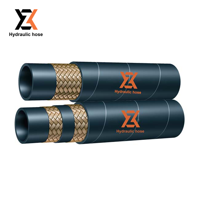
High-impulse environments mandate specific structural engineering. Spiral hoses provide the necessary foundation for these brutal applications. Unlike braided designs, spiral construction layers high-tensile steel wires parallel to one another. They wrap around the inner tube at a specific angle, separated by thin layers of bonding rubber. This design eliminates the friction points inherent in woven braids. When a pressure surge expands the hose, the parallel wires stretch uniformly without grinding against each other. This structural advantage makes spiral reinforcement the mandated solution for heavy earthmoving equipment, mining machinery, and industrial presses.
The number of reinforcement layers dictates the ultimate pressure capacity and the physical stiffness of the line. A 4-wire spiral hose features four alternating layers of parallel, wrapped high-tensile steel wire. It handles severe pressure spikes effectively while maintaining moderate flexibility for routing through articulated joints. A 6-wire spiral hose adds two additional layers. This configuration exponentially increases the burst strength and impulse resistance, making it suitable for ultra-high-pressure hydrostatic drives. The alternating wrap directions balance the torsional forces during pressurization, keeping the hose stable and preventing it from twisting under extreme loads.
Industry standards like SAE J517, EN 856, and ISO 18752 define constant pressure classes and testing protocols. Manufacturers test a heavy duty hydraulic hose by subjecting it to brutal laboratory conditions. They apply pressure spikes up to 133% of the working pressure at elevated temperatures (often 212°F or higher). A standard braided hose might survive 200,000 cycles before bursting. A premium spiral hose must exceed 500,000 to 1,000,000 cycles to pass certification. These hoses also carry critical safety certifications, such as MSHA flame resistance, ensuring reliability and operator safety in hazardous underground mining environments.
Sizing a hose for pressure pulses requires a step-by-step technical framework. You cannot rely on static pump pressure alone. You must evaluate flow velocity, calculate pressure drop over the length of the run, and factor in the spike multiplier. This systematic approach ensures the selected hose delivers the required impulse life and prevents catastrophic blowouts in the field.
Begin by balancing the flow rate (Gallons Per Minute) against fluid velocity limits. Engineers use a hydraulic nomograph to determine the correct inside diameter. Pressure lines typically require fluid velocities between 15 and 20 feet per second. Exceeding this limit causes turbulent flow. Turbulent flow generates excessive heat, degrades the inner tube, and creates backpressure that robs the system of power. You must also integrate calculations for pressure drop over long hose runs. Minimizing pressure drop ensures downstream pressure stability during rapid, high-impulse valve shifts.
Identify the maximum flow rate (GPM) of the specific circuit.
Determine the target fluid velocity (e.g., 20 ft/sec for high-pressure lines).
Use a nomograph or the formula: Area = (GPM x 0.3208) / Velocity to find the minimum inside diameter.
Calculate the pressure drop based on fluid viscosity, hose length, and the calculated diameter.
Upsize the diameter if the pressure drop exceeds 10% of the system operating pressure.
Pulse applications require a strict engineering rule of thumb. You must select a hose with a maximum working pressure rating that exceeds the system's normal operating pressure. Typically, you need a rating that is 120% to 150% of the normal pressure. This buffer absorbs transient spikes safely. If a hydraulic press operates at 4,000 PSI, the transient spikes might hit 5,500 PSI. Selecting a 6,000 PSI rated hose prevents premature fatigue and ensures the steel reinforcement does not yield during the shock wave.
Translate the calculated inside diameter into industry-standard dash sizes. The dash system measures the inside diameter in sixteenths of an inch. A -12 hose has a 3/4-inch I.D., while a -16 hose has a 1-inch I.D. The dash size directly impacts fluid velocity and system response times. It also dictates the physical footprint of the spiral hose. Larger dash sizes require more routing space, larger mounting clamps, and significantly larger bend radii.
Field verification is critical before cutting and crimping. Read and interpret the layline markings printed along the hose jacket. These markings display the manufacturer code, nominal dash size, maximum working pressure, and agency specification listings (like SAE 100R15 or EN 856 4SH). Cross-reference these printed details with your engineering specifications. This quick check verifies the actual hose parameters and prevents the accidental installation of an underrated component on a high-pressure circuit.
Specifying highly reinforced spiral hoses involves conceptual and physical trade-offs. You gain immense pressure capacity and impulse life, but you sacrifice flexibility and increase the overall weight of the machine. System engineers must analyze these factors to optimize the hydraulic circuit without creating new mechanical problems during assembly or operation.
Pressure capacity and flexibility share an inverse relationship. Adding wire layers makes the hose stiffer. Forcing a 6-wire spiral hose into a tight bend radius is dangerous. It pre-stresses the outer steel wires on the outside of the bend before the system even pressurizes. When a pressure pulse hits this pre-stressed area, the wires fatigue rapidly. This drastically reduces the impulse life of the assembly. Always adhere to the manufacturer's published minimum bend radius. If the space is too tight, use steel tube assemblies or angled fittings to navigate the corner.
Spiral hoses exhibit significantly lower volumetric expansion than braided hoses. When pressure spikes, the stiff spiral layers resist ballooning. This rigidity improves actuator responsiveness because fluid energy transfers directly to the cylinder rather than expanding the hose walls. However, there is a trade-off. Because the hose does not expand to absorb the shock, the system's relief valves, accumulators, and pump seals must absorb more of the shock wave energy. You must ensure these components are rated for high-shock duty.
Multi-layer steel wire construction adds substantial physical weight. A high pressure spiral hose requires robust clamping and support structures. During violent pulse events, the heavy hose can whip and vibrate aggressively. Proper routing and heavy-duty, rubber-lined clamps prevent this movement. Failing to secure the hose leads to severe abrasion against machine frames, eventual outer cover failure, and wire corrosion.
Proper sizing means nothing if the installation fails. Common points of failure during assembly and routing negate all the engineering work. Recognizing these implementation realities ensures the hydraulic circuit performs as designed in the dirt and mud.
High-pressure spiral hoses require specific bite-to-the-wire or skive fittings. The fitting teeth must penetrate the rubber cover (or the cover must be skived off) to grip the steel wire directly. Mixing hose and fitting brands in high-pulse applications carries catastrophic risks. Different manufacturers use slightly different tolerances for their wire diameters and rubber thickness. Intermixing components often results in a blown-off fitting during a severe pressure spike. Always use strictly matched and validated hose-to-fitting crimp specifications provided by the manufacturer.
Twisting a hose during installation is a fatal error. A twist of just 5 degrees can reduce the impulse life of a spiral hose by up to 70%. The twist misaligns the parallel wire reinforcement, creating weak points where the wires separate under pressure. Use the printed laylines as visual guides to ensure the hose remains straight during tightening. Utilizing swivel fittings at one end of the assembly allows the hose to find its natural resting position before you apply the final torque.
External abrasion from system vibration is a leading cause of physical failure. When hoses rub against each other or metal brackets, the rubber cover wears away, exposing the steel wire to rust and degradation. You must install external protective spiral wraps or nylon sleeves. Size these guards carefully. They must be large enough to accommodate the dynamic outer diameter expansion of the hose during major impulse cycles. A wrap that is too tight restricts movement, traps dirt, and causes internal friction.
| Hose Outer Diameter (O.D.) | Recommended Wrap Inner Diameter (I.D.) | Clearance for Volumetric Expansion |
|---|---|---|
| 0.75 inches | 0.85 - 0.90 inches | 0.10 - 0.15 inches |
| 1.00 inches | 1.15 - 1.20 inches | 0.15 - 0.20 inches |
| 1.50 inches | 1.70 - 1.75 inches | 0.20 - 0.25 inches |
| 2.00 inches | 2.25 - 2.30 inches | 0.25 - 0.30 inches |
Map your system's duty cycle to understand the frequency and severity of pressure spikes before selecting a hose.
Utilize digital oscilloscopes to measure actual pressure spikes in the field, rather than relying on static pump ratings.
Consult manufacturer-specific crimp charts to guarantee fitting compatibility and prevent blowout hazards.
Verify the minimum bend radius of the selected spiral hose and adjust your machine routing or use angled fittings to prevent wire stress.
A: Braided hoses use interwoven wires that cross over each other, which causes friction and metal fatigue under high pressure surges. Spiral hoses use parallel wrapped layers of high-tensile steel wire. This parallel design eliminates wire-to-wire friction, making spiral construction required for surviving high-pressure pulses.
A: The dash size system represents the inside diameter of the hose in sixteenths of an inch. For example, a -8 hose is 8/16 or 1/2 inch. You calculate the required dash size by determining the necessary flow rate (GPM) and keeping the fluid velocity within safe limits using a hydraulic nomograph.
A: Yes. Heavy-duty 6-wire spiral hoses are engineered to handle ultra-high pressures. Depending on the specific dash size and construction, they are fully capable of safely handling operating pressures up to and exceeding 10,000 PSI in severe applications like hydrostatic drives.
A: A pressure pulse is a transient, millisecond spike in fluid pressure. These violent surges are caused by sudden directional valve shifts, rapid load changes, or cylinders bottoming out. They frequently exceed the system's normal operating pressure significantly.
A: Bending a hose tighter than its specified minimum radius pre-stresses the steel wire reinforcement on the outside of the curve. When pressure pulses hit this stressed area, the wires fatigue rapidly. This drastically reduces the impulse life of the hose and leads to premature failure.
A: Failures often occur due to improper crimp diameters, a lack of skiving on heavy spiral hoses, or mismatched fitting geometries. If the fitting does not properly bite into the steel wire, it cannot hold the hose during the violent volumetric expansion caused by pressure spikes.
A: Calculate the wrap size by measuring the maximum outer diameter of the spiral hose. You must add extra clearance to accommodate the dynamic volumetric expansion that occurs during peak pressure pulses. A wrap that is too tight will restrict the hose and cause friction.


