

Views: 0 Author: Site Editor Publish Time: 2026-11-19 Origin: Site


Installing the wrong hydraulic line leads to catastrophic blowouts. It means extended downtime, ruined equipment, and severe safety hazards on the job site. You know a reliable braided flex hose keeps your fluid transfer systems running smoothly. But how many wire layers do you actually need? Over-engineering wastes your project budget. Under-engineering invites disaster.
Selecting the correct reinforcement layer is a critical engineering decision. The structural integrity of the braided matrix dictates the maximum working pressure, impulse resistance, and overall lifespan of the assembly. In this comprehensive guide, we will explore exact layer requirements. We will cover the specifications and practical field scenarios necessary to guide your final purchasing choice.
Before diving into the technical specifications, here is a brief overview of the primary configurations used across industrial fluid power applications:
One Layer - Single Braid: Engineered for medium-pressure applications. It prioritizes flexibility and tight routing capabilities. This makes it ideal for compact machinery.
Two Layers - Double Braid: Recognized as the industry standard for high-pressure systems. This design offers superior durability and resistance to aggressive hydraulic impulses.
More Than Two Layers: When systems require four or six layers of reinforcement, manufacturers typically transition from a woven braided design to a spiral wire design. These are reserved for extreme-pressure environments where raw strength supersedes flexibility.
The Decision Matrix: The optimal number of layers depends entirely on empirical data. You must evaluate your system maximum operating pressure, the required minimum bend radius, environmental abrasion factors, and project budget.
To truly grasp why the number of wire layers matters, you must examine the fundamental construction of a hydraulic conduit. A standard assembly is manufactured using a precise three-tier composite structure. This design balances fluid retention, structural strength, and environmental protection.
First, the innermost layer comes into direct contact with the hydraulic fluid. It is typically extruded from synthetic rubbers like Nitrile to ensure chemical compatibility, prevent fluid degradation, and maintain a seamless, leak-free passage. Positioned directly over this tube is the reinforcement layer. Consisting of woven high-tensile steel wires, this braided skeleton acts as the structural backbone of the line. It determines the capacity to withstand internal hydrostatic pressure and external mechanical stress. Finally, the outer cover shields the internal reinforcement from job-site hazards. Made from durable synthetic compounds like Neoprene, it provides a robust barrier against abrasion, ozone, UV radiation, and harsh chemicals.
Recent industry analyses indicate a massive shift toward high-pressure, ultra-compact hydraulic systems in both mobile equipment and industrial automation sectors. Machinery is becoming smaller yet exponentially more powerful. Consequently, the demand for lines that can handle extreme pressures without sacrificing bend radius has surged. Manufacturers are innovating with advanced metallurgical techniques to create thinner, higher-tensile wire braids. This ongoing evolution is slowly blurring the traditional performance lines between standard single and double-layer capabilities. Modern fluid power systems can now achieve higher efficiencies in much tighter spatial footprints.
In fluid power networks, reinforcement materials generally fall into two categories: textile and steel wire. Fabric braids are suitable for low-pressure applications, but they lack the structural rigidity required for demanding industrial hydraulics. Specifically, a Wire Braided Hydraulic Hose delivers superior tensile strength, exceptional burst resistance, and high kink resistance. The steel wires are woven in a precise crisscross pattern, typically engineered to a neutral angle of approximately 54 degrees and 44 minutes. This specific geometry ensures that when the line is pressurized, volumetric expansion and longitudinal contraction are minimized. This prevents premature metal fatigue.
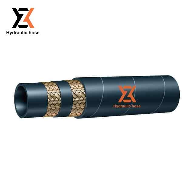
Let us look at medium-pressure hydraulic circuits. A single layer of high-tensile steel wire provides the perfect equilibrium between burst strength and operational flexibility.
The most universally recognized single-wire specification is the SAE 100R1A hose, often cross-referenced with DIN EN 853 1ST or 1SN standards. The pressure rating of this configuration is inversely proportional to its internal diameter. For instance, a 1/4-inch internal diameter single-wire line may safely operate at pressures up to 3,270 PSI. In contrast, a larger 1-inch variant of identical construction will have a maximum working pressure closer to 1,280 PSI. Technicians must always consult the exact specification tables to verify compatibility with peak system loads.
The primary advantage of a single-braid setup is its maximum flexibility. With only one layer of steel, the assembly maintains a remarkably tight minimum bend radius. Imagine routing a hydraulic line through the crowded engine compartment of a compact skid-steer loader. The pliability of a single-layer hose allows technicians to navigate complex machinery spaces without exerting excessive force or stressing the crimped fittings. Furthermore, the reduced metal content lowers the overall weight. This significantly benefits mobile equipment requiring extensive routing.
These assemblies are highly recommended for return lines, standard agricultural machinery, and light industrial equipment where pressure spikes are minimal and infrequent.
When a fluid power system operates under intense pressure or experiences frequent hydraulic hammering, a single layer of reinforcement quickly becomes insufficient. Hydraulic hammering involves rapid, violent pressure spikes. In these demanding environments, the double-braided configuration steps in as the undisputed industry standard.
The standard specification for this robust design is the SAE 100R2AT or DIN EN 853 2SN. Upgrading to a two wire braided hydraulic hose incorporates a second layer of high-tensile steel wire woven directly over the first. These layers are typically separated by a microscopic friction layer of rubber. This addition exponentially increases the structural integrity and burst pressure threshold. A 1/4-inch internal diameter two-wire assembly can handle continuous working pressures up to 5,800 PSI. This nearly doubles the capacity of its single-wire counterpart. In addition, these components undergo rigorous impulse testing, surviving upward of 200,000 cycles to ensure absolute reliability under dynamic stress.
The dual layers of steel provide a robust physical barrier against external impacts. They offer enhanced crush resistance on rugged job sites. This makes the two-wire configuration the absolute workhorse of the heavy equipment industry. It is the default choice for excavators, wheel loaders, high-pressure industrial power units, and any setting where lines endure severe external physical stress combined with high internal hydrostatic loads.
A common inquiry among procurement managers is whether a braided flex hose can be manufactured with three, four, or even six layers of wire for extreme applications. This brings us to a vital distinction in manufacturing techniques.
While it is technically feasible to weave multiple layers, systems demanding four to six layers of reinforcement almost exclusively utilize a spiral wrap design rather than a woven braid. In a standard braided design, the intersecting wires cross over and under each other. Under extreme pressure and high-frequency impulses, these intersections generate internal friction. This eventually causes the wires to fatigue and snap. Conversely, in a spiral configuration, the wires are laid parallel in alternating layers. This entirely eliminates wire-to-wire friction. Therefore, upgrading beyond two layers generally means shifting from the braided category into the spiral category.
Selecting the appropriate reinforcement layer directly impacts operational safety, system longevity, and maintenance overhead. The industry universally relies on the STAMPED method as a foundational framework: Size, Temperature, Application, Material, Pressure, Ends, Delivery. Within this framework, determining your layer configuration hinges on four specific technical parameters.
The most crucial parameter is the maximum operating pressure of your hydraulic circuit. Fluid power systems are rarely static. They experience rapid pressure fluctuations, sudden valve closures, and heavy load shifts that create dynamic spikes. You must account for the absolute peak transient pressures, not just the continuous baseline. If your system operates at 2,000 PSI but experiences transient spikes up to 3,500 PSI, a single-layer hose will degrade rapidly. Upgrading to a wire braid hydraulic hose with dual layers ensures the assembly can absorb the hydraulic shock without compromising the inner tube structural integrity.
Adding layers of steel increases pressure capacity, but it fundamentally alters the mechanical properties of the assembly. The minimum bend radius is the smallest radius at which a line can be bent without causing structural damage or kinking. When you introduce a second layer of braided steel, the friction between the wire layers and the added material thickness significantly increases stiffness. Forcing a stiff, multi-layer line into a constrained footprint causes immense stress on the outer cover and fittings. If a tight bend radius is non-negotiable but higher pressure is required, engineers must source specialized high-flex dual-layer products utilizing advanced weaving techniques.
The physical mass of the assembly is an often-overlooked factor. It becomes highly relevant in mobile hydraulics and aerospace. Steel wire is heavy. Transitioning to a double-layer configuration inherently increases the mass of the fluid transfer network. On the articulating boom of a cherry picker, the cumulative weight of multiple heavy-duty lines can impact fuel efficiency. It alters the machine center of gravity and places unnecessary mechanical strain on mounting brackets.
The external environment plays a massive role in component degradation. The synthetic rubber cover is the primary line of defense against UV radiation and physical abrasion. However, the underlying wire braid provides a secondary structural barrier. In harsh environments like underground mining, lines are frequently dragged across abrasive rock. A double-layer configuration offers a slightly thicker skeleton, providing a marginal buffer before the fluid-carrying tube is compromised. Relying on the wire braid for abrasion resistance is a dangerous practice. Protective nylon sleeves or spiral guards should always be utilized in high-wear zones.
For procurement professionals evaluating the total cost of ownership, choosing between a single and double wire braid requires balancing upfront costs against long-term reliability. Below is a quick comparison to guide your engineering decisions.
| Feature | Single Wire Braid | Double Wire Braid |
|---|---|---|
| Pressure Rating | Medium up to 3,270 PSI for 1/4 inch | High up to 5,800 PSI for 1/4 inch |
| Flexibility | Excellent tight bend radius | Moderate stiffer construction |
| Weight | Lightweight | Heavier |
| Best Application | Return lines, compact machinery | Excavators, high-stress power units |
From a strictly financial perspective, a single-layer hose is more economical to manufacture and purchase. For static, low-stress return lines, utilizing a single-layer configuration makes perfect economic sense. However, if a single-layer variant is installed in an application that pushes the upper limits of its pressure rating, accelerated wear will lead to premature failure. The cost of machine downtime, environmental cleanup from fluid loss, and emergency replacement labor far exceeds the initial savings.
The Engineering Rule of Thumb: If your hydraulic system routinely peaks over 3,000 PSI, experiences aggressive hydraulic hammering, or operates in an environment where a burst would cause severe safety hazards, always default to a double-layer configuration. In contrast, if you are routing low-pressure pilot lines where extreme flexibility is paramount, a single-wire design remains the optimal, cost-efficient choice.
Even the highest-quality multi-layer hoses will fail prematurely if subjected to improper installation or neglected during routine maintenance. Implementing a proactive inspection protocol is essential for maximizing operational lifespan.
Visual inspections should be conducted at regular intervals to identify early warning signs. Look for cracked or hardened covers caused by heat exposure, weeping fluid around the crimped connections, or unnatural stiffening. If physical abrasion has worn away the outer rubber and exposed the steel wire braided hose reinforcement underneath, the assembly must be replaced immediately. Exposed wires will rapidly oxidize. They lose their tensile strength and compromise the pressure rating entirely.
Furthermore, avoid torsional stress during installation. Twisting a hose forces the braided wire layers out of their engineered alignment. A twist of just 7 degrees can reduce the lifespan of a high-pressure line by up to 90 percent. Technicians must utilize the printed layline as a visual guide to ensure the component remains perfectly straight once the fittings are torqued down.
Choosing the right braided flex hose is paramount for ensuring system safety and operational efficiency. It is crucial to remember that more wire layers do not automatically equate to better performance. Success lies in matching your engineering specifications directly to the demands of your application. An SAE 100R1A configuration handles flexible, medium-pressure needs perfectly. Meanwhile, a double-layer setup manages aggressive, high-pressure environments effectively.
Take the time to evaluate your hydraulic system requirements carefully. By understanding the dynamic pressures, routing constraints, and environmental hazards of your specific job site, you can select the exact reinforcement configuration needed to keep your machinery running safely and profitably. Need help matching the exact reinforcement configuration for your next project? Browse our high-performance fluid power solutions and find the exact specifications for your machinery at Zhongxu Hose today.
The primary difference lies in the structural reinforcement layer and subsequent pressure capabilities. The SAE 100R1A features a single layer of braided high-tensile steel wire. This makes it highly flexible and suitable for medium-pressure applications. In contrast, the SAE 100R2AT is engineered with two layers of braided steel wire. This additional layer significantly increases the structural rigidity, durability, and maximum working pressure. It is the standard for high-stress industrial machinery.
No. Utilizing a single-layer hose in a hydraulic system that generates pressures exceeding the maximum working rating is a severe safety violation. When over-pressurized, the single layer of wire braid cannot contain the hydraulic force. This leads to rapid structural fatigue, catastrophic blowouts, dangerous fluid injection injuries, and extensive equipment downtime.
Yes. Every additional layer of steel wire inherently increases the mechanical rigidity of the assembly. The woven nature of the steel creates internal friction when bent. This results in a noticeably larger minimum bend radius compared to a single-layer variant of identical inner diameter. This can make multi-layer hoses difficult to route through highly compact spaces.
The operational lifespan is entirely dependent on its operating environment, fluid temperature, impulse cycle frequency, and maintenance routing. Under normal conditions, kept within specified temperature and pressure limits, a premium-quality component can last anywhere from 2 to 5 years. Preventative maintenance programs generally recommend replacing high-stress lines every 2 to 3 years to avoid unexpected failures.
The minimum bend radius is measured from the inside edge of the hose, not the centerline. You calculate it by determining the smallest circle the hose can be bent around without kinking or causing damage to the wire reinforcement. Always consult the manufacturer specification sheet, as exceeding this limit places dangerous stress on the outer cover and inner wire layers.
Technically yes, but it is not always recommended. A 2-wire hose will easily handle the pressure requirements of a 1-wire system. However, the 2-wire hose will be significantly heavier, thicker, and stiffer. If your machinery has tight routing spaces or requires frequent articulation, the added stiffness of the double-layer reinforcement could cause mechanical strain on your fittings and mounting brackets.


