

Views: 0 Author: Site Editor Publish Time: 2026-11-09 Origin: Site


Ever witnessed a fluid line violently rupture on a busy factory floor? The sudden release of intense pressure is terrifying. It is also a costly disaster that brings entire production lines to a grinding halt. Industrial equipment relies heavily on fluid power to execute heavy-duty tasks. Containing that immense kinetic energy requires specialized components. A reliable conduit must be engineered with specific materials to survive these harsh dynamic conditions. Without the right structural foundation, catastrophic failures happen in the blink of an eye.
As a fluid power engineer, I have seen firsthand what happens when inferior materials fail. In this technical guide, we will explore the exact materials that create burst strength. You will learn how different composite layers work in perfect harmony to keep your machinery running efficiently and your operators safe from hazardous blowouts.
Key Takeaways
Burst strength is primarily determined by the reinforcement layer, typically engineered from high-tensile steel wire.
A robust fluid line relies on a three-part anatomy: an inner tube, a structural reinforcement layer, and a protective outer cover.
Chemical compatibility is non-negotiable: Utilizing a specialized oil resistant hydraulic hose core prevents internal degradation that ultimately weakens the steel skeleton over time.
Connections matter: A perfectly crimped assembly utilizing compatible steel fittings is essential to maintain the rated pressure threshold.
To make informed decisions about fluid power systems, we must first grasp exactly what burst strength means within the context of fluid dynamics. Often referred to as burst pressure, this metric represents the absolute maximum internal threshold a line can withstand before its structural materials physically tear apart. It is the ultimate limit where the outward kinetic energy of the pressurized fluid overcomes the tensile strength of the reinforcement.
In the industrial manufacturing sector, distinguishing between working pressure and burst pressure is crucial for safety. Working pressure represents the maximum continuous stress the equipment is designed to handle during normal daily operations. To ensure a massive safety buffer, the industry relies on a strict safety factor. This is typically a 4:1 ratio for standard fluid power applications.
For instance, if a high pressure hydraulic hose is rated for a working pressure of 4,000 PSI, its materials are meticulously engineered to achieve a minimum burst pressure of 16,000 PSI. This safety margin accommodates sudden pressure spikes, fluid surges, and the violent water hammer effect that frequently occurs when heavy-duty valves close rapidly. Choosing a product with inadequate material strength leads to premature bursting. A ruptured line can cause severe fluid injection injuries and staggering machinery downtime.
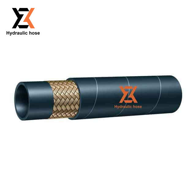
The exceptional burst strength of these industrial conduits is not the result of a single miracle material. Instead, it is the product of a meticulously engineered composite structure. Almost all reliable lines designed for intense applications share a universal three-layer architectural design. Each layer serves a distinct functional purpose.
First, the inner tube acts as the fluid-carrying core. Its primary job is containment and chemical compatibility. Second, the reinforcement serves as the muscle of the structure. Wrapped tightly around the inner tube, it provides the actual resistance to internal pressure. Finally, the outer cover acts as the protective skin. It defends the critical reinforcement layer from external environmental damage like severe abrasion or moisture.
The true resilience lies in the synergy of these three layers. During the manufacturing process, these distinct materials undergo a rigorous chemical curing process known as vulcanization. Under precise heat and pressure, the rubber compounds cross-link and bond chemically through the microscopic gaps in the wire reinforcement. This creates a unified matrix capable of withstanding dynamic fluctuations.
While the inner tube does not provide the primary burst strength, its role is absolutely foundational. Its main function is to transport the fluid efficiently while shielding the outer reinforcement layers from the fluid itself. If aggressive fluids penetrate the inner tube, they will rapidly attack the reinforcement layer. This leads to inevitable and dangerous failure.
The choice of material for the inner tube is dictated entirely by fluid compatibility. Nitrile rubber, widely known as NBR, is the most common material utilized. Nitrile rubber offers excellent resistance to petroleum-based fluids, oils, and greases. If a non-resistant rubber were used, petroleum fluids would cause the tube to swell, soften, and eventually dissolve.
Furthermore, polytetrafluoroethylene or Teflon is utilized in environments involving extreme temperatures or highly aggressive chemicals. It is nearly chemically inert. This ensures that corrosive fluids cannot reach and weaken the structural skeleton. Consequently, the impact of the inner tube on overall strength is indirect but critical. If the inner tube degrades, pressurized fluid seeps outward, causing immediate rust on steel reinforcements.
When discussing what gives a fluid conduit its burst strength, the conversation must center on the reinforcement layer. This is the structural skeleton. High-pressure industrial applications demand materials with exceptional tensile strength and remarkably low elasticity.
High-tensile steel wire is the undisputed material of choice. Steel wire provides the rigidity needed to prevent the assembly from expanding like a balloon under immense force. At the same time, it allows enough flexibility for routing through complex machinery spaces. The configuration of this steel directly determines the maximum threshold.
A single wire braided hydraulic hose is constructed by weaving a single layer of high-tensile steel wire over the inner tube. The braiding process involves weaving wire strands in an over-and-under crisscross pattern. To maximize stability, manufacturers calculate a specific neutral angle for the braid, typically around 54 degrees. At this precise angle, the line will neither elongate nor contract significantly when pressurized. Products like the SAE 100R1AT utilize this design to offer an excellent balance between burst strength and flexibility. They operate reliably in temperature ranges from minus 40 to positive 100 degrees Celsius, making them ideal for standard forklift operations.
For systems that operate at higher pressures and experience more aggressive spikes, a single layer of wire is simply insufficient. Imagine a heavy excavator lifting a multi-ton concrete slab. The fluid lines are pulsing with immense kinetic energy. In these scenarios, a double braided construction like the SAE 100R2AT is utilized. This features a second layer of braided high-tensile steel wire applied over the first. The addition of the second braided layer exponentially increases the burst strength, making it the industry standard for heavy-duty construction equipment.
While braiding is highly effective, it inherently possesses limitations. Where the braided wires cross over each other, they create friction points. Under ultra-high pressure and constant pulsing, these friction points can cause the wires to fatigue and snap. For extreme pressure applications, manufacturers use spiral wire reinforcement instead. The high-tensile steel wires are wrapped in parallel layers around the tube. Successive layers are wrapped in alternating directions to balance the torsional forces. Designs with four or six-wire spiral configurations can achieve staggering burst strengths exceeding 40,000 PSI.
To clearly illustrate how reinforcement dictates performance, consider the following comparison based on standard industry specifications:
| Reinforcement Type | Material Structure | Typical Max Working Pressure | Ideal Application Scenario |
|---|---|---|---|
| Single Wire Braid | One layer of high-tensile steel wire | Up to 3,270 PSI | Medium-duty tasks, agricultural tractors, forklifts |
| Double Wire Braid | Two crossed layers of steel wire | Up to 5,800 PSI | Heavy-duty construction, excavators, industrial presses |
| Multi-Spiral Wire | Four to six parallel wrapped steel layers | Up to 10,000+ PSI | Mining equipment, ultra-high pressure hydro-demolition |
The outer cover acts as the final line of defense. Its primary function is not to hold back internal pressure. Instead, it protects the crucial steel wire reinforcement from external environmental elements that could compromise the burst strength over time. A Wire Braided Hydraulic Hose dragged across a gravel construction site faces very different threats than one installed in a stationary indoor factory.
The materials chosen for the outer cover must withstand specific operational hazards. Synthetic rubber, such as Neoprene, is the standard cover material. It offers excellent resistance to weathering, ozone cracking, and general abrasion. The greatest threat to the reinforcement layer is undoubtedly rust. If the outer cover material fails through deep abrasion or UV degradation, moisture penetrates to the steel. Once high-tensile steel begins to oxidize, it loses its tensile strength rapidly. When the system subsequently experiences a pressure spike, these weakened wires will snap.
As industrial machinery becomes more compact and powerful, the demands placed on fluid power systems are reaching unprecedented levels. Analyzing current market trajectories reveals a significant shift in how manufacturers are approaching burst strength. The trend is moving away from simply adding more layers of heavy steel. That traditional approach increases weight and drastically reduces flexibility. Instead, the focus is shifting toward the integration of advanced composite materials and proprietary metallurgical advancements.
Specifically, metallurgical engineering is yielding ultra-high-tensile steel alloys. These new alloys offer higher burst pressure ratings with a noticeably thinner wire diameter. This advancement allows for lines that are highly flexible, easier to route in tight spaces, and significantly lighter, all without sacrificing the crucial 4:1 safety factor. In addition, there is a growing emphasis on ultra-high-molecular-weight polyethylene covers. These advanced outer layers provide extreme abrasion resistance, ensuring the structural reinforcement remains unexposed even in the most brutal mining or forestry environments. This proactive approach to material science is drastically reducing catastrophic failures across heavy industries.
A discussion about burst strength remains incomplete without addressing how the line connects to the machinery. In the fluid power sector, there is a well-known axiom. The system is only as strong as its weakest link. A properly manufactured line rarely bursts in the middle of its length. Catastrophic failures overwhelmingly occur at the connection points.
To maintain the rated burst pressure, the connection must be flawless. This requires the creation of a precise hydraulic hose assembly. The materials used in the fittings are just as critical as the core itself. Fittings are typically machined from high-grade carbon steel or stainless steel. These metals must possess the yield strength to withstand the exact same extreme pressures as the reinforcement layer.
The mechanical process that binds the fitting is known as crimping. During this critical fabrication step, a metal ferrule is compressed using a high-powered press. For high-pressure applications, it is often necessary to skive the cover. This means a portion of the outer rubber is physically removed so the metal teeth of the fitting can bite directly into the steel wire reinforcement. This direct metal-to-metal grip guarantees that the fitting will not blow off under maximum load.
Selecting the correct materials is a critical decision that directly impacts operational safety, equipment longevity, and maintenance costs. Guesswork inevitably leads to equipment failure. To ensure all variables are meticulously accounted for, industry professionals rely on the STAMPED method. This systematic approach guarantees that the selected materials will maintain their engineered burst strength in real-world conditions.
Size: The inner and outer diameter must precisely match system flow requirements to prevent internal heat buildup.
Temperature: Internal fluid heat and external environmental extremes determine the necessary rubber compounds to prevent thermal cracking.
Application: Where and how the equipment is utilized dictates the need for specialized abrasion-resistant covers.
Material: Fluid compatibility strictly dictates the type of inner tube required to prevent internal swelling.
Pressure: The maximum system working pressure and potential dynamic spikes directly dictate the reinforcement material. This steers the choice between single wire, double wire, or multi-spiral steel.
Ends: Ensuring the fitting material matches the system requirements prevents blow-offs.
Delivery: Consistent high-velocity delivery requires materials that resist internal erosion.
The burst strength of a fluid power line is a true marvel of modern material science. It is not merely a thick rubber tube, but a highly sophisticated composite structure. Oil-resistant inner tubes, high-tensile steel wire reinforcements, and rugged outer covers must work perfectly together to contain immense kinetic energy.
Understanding these durable materials empowers technical buyers and maintenance engineers to select the right equipment for their specific needs. Proper selection ensures workplace safety, prevents costly environmental spills, and greatly extends your machinery's operational lifespan. Always take the time to inspect your current fluid lines for any signs of abrasion, cracking, or exposed wire. When it is time to upgrade or replace your hydraulic assemblies, ensure your materials are up to the task. For reliable, field-tested solutions engineered for maximum burst strength, explore the comprehensive range of premium products at Zhongxu Hose to find the exact specifications your heavy-duty machinery demands.
Working pressure is the maximum continuous internal pressure the equipment is designed to handle safely on a daily basis. Burst pressure is the absolute maximum pressure the materials can withstand before physically exploding. For safety reasons, burst pressure is usually designed to be four times the working pressure.
Depending on the operating environment, fluid temperature, and preventative maintenance, a quality wire braided product can last anywhere from two to five years. However, severe UV exposure, extreme temperature fluctuations, and heavy physical abrasion can significantly shorten this lifespan.
No. While a single wire braided design is highly flexible and strong enough for medium-duty tasks, heavy-duty industrial equipment often requires double-braided or multi-spiral wire reinforcements. These heavier structures are necessary to safely handle extreme pressure spikes and mechanical impulses.
Leaks at the fitting usually indicate an improper crimp, mismatched fitting materials, or a failure of the inner tube material near the connection point. A leaking fitting severely compromises the burst strength of the entire system and requires the immediate replacement of the assembly.
If the damage is purely cosmetic to the outer cover and the wire is unseen, it might be monitored safely. However, if the steel wire reinforcement is exposed, rusted, or frayed, the burst strength is permanently compromised. The unit must be replaced entirely. Never attempt to patch a high-pressure fluid line.
Premature bursts are typically caused by selecting a product with an inadequate pressure rating for the system's pressure spikes. Other common causes include severe abrasion that exposes the steel wire to rust, improper crimping of fittings, or chemical degradation of the inner tube due to incompatible hydraulic fluids.
Manufacturers conduct destructive hydrostatic testing. A sample assembly is filled with water or a specialized testing fluid, and the internal pressure is steadily increased using a high-powered pump until the structural materials physically fail and rupture. This ensures the batch meets the strict 4:1 safety factor required by international standards.


