

Views: 0 Author: Site Editor Publish Time: 2026-07-24 Origin: Site


Catastrophic hose failure in high-pressure fluid and pneumatic systems introduces severe operational risks. Ruptured lines cause immediate fluid loss, environmental contamination, and safety hazards for on-site personnel. Over-specifying hoses leads to unnecessary weight and inflated procurement costs. Under-specifying compromises system integrity and guarantees unplanned downtime. Selecting the correct hose requires moving beyond basic inner and outer diameter measurements. Engineers must conduct a rigorous analysis of dynamic pressure data, environmental factors, and structural limits. You cannot rely on nominal ratings alone. System relief valve settings, pressure spikes, and thermal degradation all dictate the actual performance envelope of the assembly. This guide breaks down the exact pressure metrics required to specify a reliable assembly. We cover dynamic loading, temperature derating, and structural limits to ensure your next fluid power design operates safely under peak demand.
Working Pressure vs. System Max: A hose’s maximum working pressure must exceed the system’s maximum relief valve setting by a minimum baseline of 25%, adjusting upward for dynamic loads.
Burst Pressure Realities: Burst pressure ratings are manufacturing benchmarks for safety margins, not operational limits; systems should never intentionally approach these thresholds.
Temperature Derating: Pressure capabilities of resin materials degrade at elevated temperatures; precise thermal data is required to calculate accurate derating factors.
Dynamic vs. Static Loading: Pressure spikes, surges, and cyclic loading dictate the required reinforcement structure, making fiber-reinforced options ideal for specific fatigue-resistance profiles.
A successful hose specification achieves zero leaks and optimal lifespan while complying with strict safety standards. You must match the physical capabilities of the hose to the exact demands of the hydraulic or pneumatic circuit. Failure to align these metrics results in premature fatigue. Success means the hose absorbs system shocks, resists environmental degradation, and maintains volumetric integrity over thousands of operational cycles. We measure this success by tracking the mean time between failures on active equipment. If a line blows out after three months on a mobile excavator, the initial pressure analysis was flawed. You need components that handle the actual field conditions, not just the theoretical baseline.
Industry professionals use the S.T.A.M.P.E.D. acronym to guide hose selection. This stands for Size, Temperature, Application, Material, Pressure, Ends, and Delivery. Pressure acts as the ultimate design constraint within this framework. If the pressure rating falls short, the other variables cannot compensate. You must lock in the pressure requirements first before evaluating material compatibility or end fittings. When we design a new hydraulic circuit, we map out the pressure profile before looking at anything else. A line might fit perfectly and handle the ambient heat, but if it cannot survive the pressure spikes from a directional control valve snapping shut, it will fail.
Maximum Working Pressure (MWP) represents the highest continuous pressure the hose can safely handle. Manufacturers calculate MWP based on the structural limits of the inner tube and reinforcement layers. It serves as your primary baseline for continuous operation. Your system's normal operating pressure should never exceed this value. Operating continuously at or near the MWP reduces the overall service life of the assembly. We always aim to keep the standard operating pressure well below the MWP. This buffer absorbs minor fluctuations and extends the operational life of the thermoplastic core.
Burst pressure is the exact point where the hose structurally fails and ruptures. The industry relies on standard safety ratios, typically 4:1 for hydraulics and 3:1 for pneumatics. A 4:1 ratio means the burst pressure is four times higher than the MWP. Burst testing is a destructive validation method used in manufacturing. It is not an operational guideline. You should never design a system to operate anywhere near the burst pressure threshold. If a line has a 10,000 PSI burst rating, its MWP is 2,500 PSI. Pushing the system to 4,000 PSI just because the burst rating is high guarantees a catastrophic blowout.
Proof pressure typically sits at twice the working pressure. Manufacturers use this metric for factory assembly testing and quality assurance. Technicians pressurize the completed hose assembly to the proof pressure and hold it there for a specific duration. This non-destructive test verifies the integrity of the crimped fittings and the core tube before the product ships to the field. We run proof tests on every single assembly built in the shop. It catches bad crimps and hidden defects in the reinforcement layers before the line ever sees active service.
Gathering steady-state operating pressure data is your first step. However, steady-state pressure does not tell the whole story. You must identify the absolute maximum pressure dictated by the system's relief valves. Relief valves act as the safety net, opening only when pressure exceeds a set limit. Your hose's MWP must exceed this relief valve setting by at least 25 percent to ensure adequate safety margins during fault conditions. If your relief valve pops at 3,000 PSI, your line needs an MWP of at least 3,750 PSI. Anything less leaves you vulnerable to pressure spikes before the valve fully opens.
Fluid traveling through a hose experiences friction, leading to a drop in pressure from the inlet to the outlet. Hose length and inner diameter directly influence flow velocity and cumulative pressure drops. A smaller inner diameter increases velocity and friction, causing a higher pressure drop. You must calculate this drop to determine the required inlet pressure. If the drop is too high, the system will not deliver adequate power to the actuators. We use specific formulas to calculate this loss based on fluid viscosity and flow rate.
| Inner Diameter (Inches) | Flow Rate (GPM) | Fluid Velocity (ft/sec) | Estimated Pressure Drop (PSI per 100 ft) |
|---|---|---|---|
| 0.25 | 5 | 32.6 | 450 |
| 0.50 | 5 | 8.1 | 85 |
| 0.75 | 15 | 10.8 | 110 |
| 1.00 | 30 | 12.2 | 95 |
Static systems maintain steady pressure with minimal fluctuations. Dynamic systems experience rapid pressure changes, surges, and hydraulic hammer effects. Valves opening and closing rapidly create severe pressure spikes that exceed normal operating levels. Standard mechanical gauges cannot capture these transient peaks. You must use electronic pressure transducers with high sampling rates to measure the true magnitude of dynamic loading in your circuit. We hook up transducers to the test ports and log the data at 1,000 samples per second. This reveals spikes that are completely invisible on a standard dial gauge.
Some applications require suction or vacuum resistance. Negative pressure impacts the inner tube differently than positive pressure. Positive pressure pushes outward against the reinforcement. Vacuum pulls the inner tube inward, risking collapse. You must verify the specific vacuum rating of the hose. Standard high-pressure lines may not possess the structural rigidity required to withstand severe negative pressure without an internal support spring. If you run a high-pressure line on the suction side of a pump without checking the vacuum rating, the core will collapse and starve the pump.
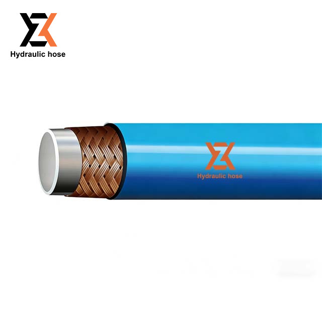
Engineers typically choose between traditional wire-braided rubber hoses and fiber-reinforced resin alternatives. Rubber hoses offer robust external abrasion resistance but carry significant weight. A lightweight pressure hose utilizes synthetic fibers and thermoplastic cores. This approach drastically reduces weight while maintaining high burst pressure ratings, making them ideal for mobile equipment and robotic applications. When outfitting a boom lift, shedding fifty pounds of hose weight directly increases the safe working load of the basket.
High-performance thermoplastics define the capabilities of modern resin hoses. Nylon 11 and Nylon 12 dominate the inner core market. These materials offer exceptional resistance to high-pressure pneumatic gases and aggressive chemicals. Unlike rubber, nylon does not degrade rapidly when exposed to synthetic hydraulic fluids or solvents. This chemical stability ensures the inner tube maintains its structural integrity under high pressure. We specify nylon cores for paint spray rigs and chemical injection skids because standard rubber swells and fails within weeks.
The reinforcement layer dictates the pressure capacity of the hose. Manufacturers braid or spiral aramid, polyester, or nylon fibers around the inner core. These high-tensile fibers distribute hoop stress evenly across the hose structure when pressurized. Aramid fibers provide immense strength-to-weight ratios. This allows the hose to handle extreme pressure spikes while maintaining a tight bend radius and overall flexibility. You can route an aramid-reinforced line through tight bulkheads where a steel-braided line would kink and fail.
When pressurized, hoses expand slightly. A high pressure resin hose exhibits significantly lower volumetric expansion compared to a standard rubber hose. Lower expansion means the fluid energy transfers directly to the actuator rather than ballooning the hose. This results in faster system response times, reduced hydraulic lag, and highly precise fluid control in sensitive applications. We use low-expansion lines on CNC clamping fixtures. If the line balloons, the clamp pressure drops, and the workpiece shifts during machining.
Every engineering choice involves trade-offs. A Fiber Reinforced Resin Hose offers easier routing, tighter bend radii, and lower equipment payload. This is highly beneficial in automotive and mobile applications. However, fiber-reinforced resin hoses can be more susceptible to external abrasion compared to steel-braided variants. You must often specify protective sleeves or spring guards if the hose will rub against abrasive surfaces in the field. We wrap exposed lines in nylon chafe sleeves to prevent the outer jacket from wearing through against the machine chassis.
Thermal data directly intersects with pressure ratings. You cannot evaluate pressure capacity in a vacuum. As temperatures rise, the structural integrity of thermoplastic materials softens. This softening reduces the hose's ability to contain high-pressure fluids safely. Evaluating the maximum ambient and fluid temperatures ensures you select a hose that maintains its required burst strength throughout the operational cycle. A line rated for 5,000 PSI at room temperature will blow out at 3,500 PSI if the hydraulic oil hits 180 degrees Fahrenheit.
You must apply derating factors when operating above ambient room temperature. Manufacturers provide specific derating multipliers for nylon, polyurethane, or fluoropolymer inner cores. You multiply the nominal MWP by the manufacturer's temperature factor to find the true safe working pressure for your specific thermal environment. We keep derating charts taped to the shop wall to ensure nobody specs a line without running the thermal math first.
| Operating Temperature (°F) | Nylon Core Derating Multiplier | Polyurethane Core Derating Multiplier |
|---|---|---|
| 70°F | 1.00 | 1.00 |
| 100°F | 0.85 | 0.80 |
| 130°F | 0.70 | 0.65 |
| 150°F | 0.60 | 0.50 |
| 180°F | 0.50 | Not Recommended |
Internal fluid temperature is only half the equation. External environmental stressors severely impact longevity. Prolonged UV exposure degrades thermoplastic jackets, causing them to become brittle and crack. Harsh chemical washdowns strip away protective layers. Ambient heat from nearby exhaust manifolds bakes the hose. These external factors degrade the outer jacket and reinforcement layers over time, indirectly lowering the effective burst pressure and risking sudden failure. We route lines away from exhaust stacks and use UV-resistant jackets for any equipment stored outdoors.
Industry standards provide a uniform evaluation lens for hose performance. ISO 4414 governs safety requirements for pneumatic systems, while SAE J517 outlines specifications for hydraulic hoses. These protocols dictate exact pressure testing methods, dimensional tolerances, and performance benchmarks. Specifying hoses that meet or exceed these standards guarantees a baseline level of safety and reliability. We reject any component that lacks clear SAE or ISO markings on the layline.
Static burst tests do not replicate real-world conditions. Impulse testing simulates the violent pressure spikes found in dynamic systems. Manufacturers subject hoses to rapid pressure cycles, often surviving 200,000 to 500,000 cycles at 133% of the working pressure. Reviewing this impulse test data is mandatory. It verifies the fatigue resistance of the fiber reinforcement and ensures the hose will not fail prematurely under heavy cyclic loading. A line might hold 5,000 PSI static all day, but fail after 10,000 cycles of hydraulic hammer.
Never procure high-pressure components without proper documentation. You must request material test reports and pressure test certificates from the manufacturer. These documents provide traceability back to the raw materials and prove the specific batch passed all required proof and burst tests. Traceability protects your operation from counterfeit products and provides necessary documentation for safety audits and compliance inspections. We file the test certificates for every assembly installed on lifting equipment.
Bending a hose below its minimum bend radius creates severe structural risks. It artificially increases stress on the outer curve's reinforcement fibers while kinking the inner curve. This drastically reduces the pressure capacity and leads to rapid fatigue failure. To mitigate this, you must calculate dynamic bend radii during the design phase. Utilize proper routing hardware, such as 45-degree and 90-degree adapters, to prevent tight bends near the connection points. We use drop-forged steel adapters to take the strain off the hose ends.
High-pressure blow-offs frequently occur when mismatched fittings are crimped onto resin hoses. Thermoplastic hoses require specific fitting geometries that bite into the core tube differently than rubber hose fittings. Using incorrect fittings compromises the crimp integrity. You must mandate the use of manufacturer-specified, matched hose-and-fitting systems. Never mix and match brands between the hose and the crimp fittings. We scrap any assembly where the technician used a fitting from a different manufacturer.
Latent structural damage or assembly errors during the fitting installation phase can cause immediate field failures. Visual inspections are insufficient. You must implement hydrostatic pressure testing of complete assemblies before installation. Use specialized pressure test rigs to pressurize the assembly to its proof pressure using water or a safe test fluid. Hold the pressure for the specified duration and inspect for any weeping or fitting slippage. We follow a strict testing sequence for every new line.
Connect the assembly to the hydrostatic test bench and secure the safety enclosure.
Fill the line with water and bleed all trapped air through the highest vent valve.
Ramp the pressure up to 50% of the proof pressure and hold for one minute to stabilize.
Increase the pressure to 100% of the proof pressure and hold for five minutes.
Inspect the crimp collars for any signs of fluid weeping or mechanical slippage.
Depressurize the system, drain the fluid, and cap the ends to prevent contamination.
Take the following steps to finalize your fluid power design:
Install electronic pressure transducers on your test ports to log actual dynamic pressure spikes during full-load operation.
Calculate the maximum fluid temperature and apply the corresponding derating multiplier to your required working pressure.
Specify matched fittings and crimp specifications directly from the hose manufacturer's engineering manual.
Mandate hydrostatic proof testing for all completed assemblies before they are installed on the equipment.
A: The standard safety margin is a 4:1 ratio for hydraulic applications and a 3:1 ratio for pneumatic applications. This means the burst pressure is four times higher than the maximum working pressure, providing a buffer against unexpected pressure surges.
A: Elevated temperatures soften the thermoplastic materials used in resin hoses. This softening reduces the structural strength of the inner core and jacket, requiring you to apply a derating factor to lower the maximum safe working pressure as temperatures rise.
A: Working pressure is the maximum continuous operating limit. Proof pressure is a non-destructive factory test level, usually twice the working pressure. Burst pressure is the destructive limit where the hose structurally fails and ruptures.
A: Yes, provided it is reinforced with high-tensile materials like aramid fibers. These fibers offer excellent fatigue resistance and distribute hoop stress effectively, allowing the hose to absorb severe dynamic pressure spikes without failing.
A: You must perform a hydrostatic proof test. Fill the completed assembly with water or a safe test fluid, bleed all air, and pressurize it to twice its maximum working pressure. Hold it for the manufacturer-specified time to check for leaks or fitting slippage.
A: Exceeding the minimum bend radius overstresses the reinforcement fibers on the outside of the bend and kinks the inner tube. This compromises the structural integrity, drastically reducing the hose's ability to hold pressure and leading to premature rupture.


